Switch / controller positions
Wall-control positions, room by room: per position, the exact spot and unit composition — device types (F 50 RC / F 40 / LS Touch hub, per the operating concept), frame positions/boxes, provisions, cabling — with module coverage checked against the room's functions; open items marked TBD. Each room or zone section starts with a standard one-line summary for every position; full entries follow. Per-button maps are deliberately deferred: an entry pins the spot and unit composition first and lists the position's function scope; the full maps are assigned in a later planning round.
Position codes: <zone>.<n> — the blueprint zone number (never renumbered) + a per-room ordinal, e.g. 3.1, 2.3, 11.1. A code is assigned when a position is decided; undecided spots stay "Candidate n" until then.
Rooms not listed below deliberately have no wall controls:
- Bathrooms/toilet — no electronics inside per British-derived wiring standards (BS 7671 zones, followed in Cyprus); each wet room is controlled from the closest switch position outside it: guest toilet → 6.1 in its short entry passage (pending confirmation that this is a permitted outside-control location) · master bathroom → master hallway 13.2 at its entrance · kid's bathroom → corridor 10.2 at its entrance.
- Stairs, balconies other than the chill zone, pool zone, and entrance — automation/presence-driven or controlled from adjacent positions. Master-balcony zones 21–22 are controlled from master-bedroom 14.1; the chill zone (22) additionally gets its own local wall group (zone 22).
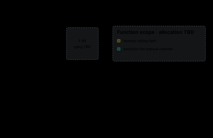
The laundry room, small as it is, keeps a minimal position at its door — the extractor-fan manual-override rule (ventilation) requires a physical button per fan.
Diagram conventions (color code, dashed = conditional/reserved): see reading the diagrams.
1. Back hallway
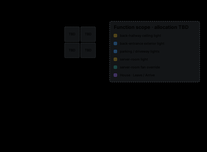
- 1.1 — Back entrance: single-position switch-height frame with one F 40 4-gang bus module.
1.1 — Back entrance
Single-position switch-height frame, one F 40 4-gang bus module (no stack).
- On the east wall, to the left of the server-room door when facing it from the back hallway — the north side of the door frame; operator faces east (house model).
- Function scope (per-button map TBD): back-hallway ceiling light · back-entrance exterior light + parking/driveway lights (zone a) · server-room light · server-room extractor-fan manual override (ventilation) · whole-house scene slots (Scene-TBD) — the car-side second entrance gets the daily-entrance pair, mirroring living-room 3.1. 6 functions against the 4-gang's 8 pressure points — fits with headroom (slaps disabled per the scene policy).
- Serves the server room: the server-room light and extractor-fan manual override (ventilation) land at this position — no wall controls inside the server room itself (see server room).
- No RC of its own — its warm-floor zone is merged with the kitchen's (climate): back hallway's floor rides the kitchen F 50 RC's loop (RC at 2.3), no independent actuator channel.
2. Kitchen
- 2.1 — Living-room door: ground-floor LS Touch hub at thermostat height and a horizontal switch-height F 40 + satellite-provision row.
- 2.2 — Street: horizontal switch-height 2-position frame with 2× F 40, for street scope only.
- 2.3 — Above counter: F 50 RC at 160 cm, the one thermostat-height exception, and F 40 at 110 cm for counter clearance.
2.1 — Living-room door
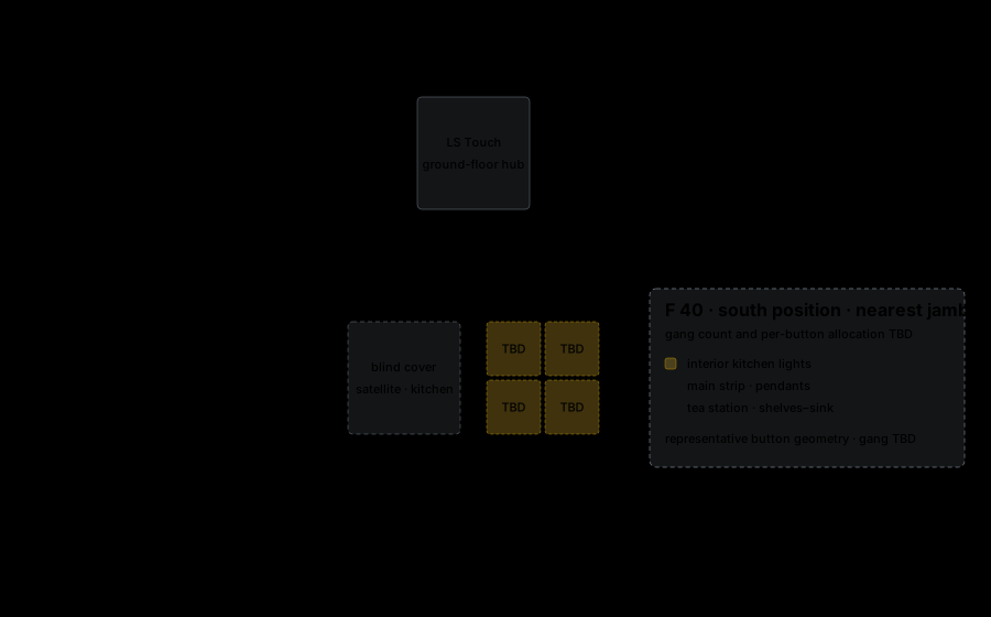
Hosts the ground-floor LS Touch hub (thermostat height) and a horizontal switch-height F 40 + satellite-provision row.
- To the left (north) of the living room door, operator faces east — back-to-back with living-room 3.2 through the shared wall.
- Thermostat height: the ground-floor LS Touch hub (wall controls) — same wall spot as the row below, centered over it (aligned group centers, one plumb column).
- Switch height: horizontal 2-position frame (the horizontal-row option) — south position, nearest the door jamb: F 40 (gang count TBD) — the interior kitchen lights (main strip · pendants · tea station · shelves–sink; per-button map TBD; most-used module nearest the jamb per the row-order convention) · north position: satellite provision (deep box + Cat6 + KNX, blind cover) = the kitchen voice satellite's home (voice), facing the island from the east. Operator faces east → south on the right.
- Gang count and per-button map TBD.
2.2 — Street
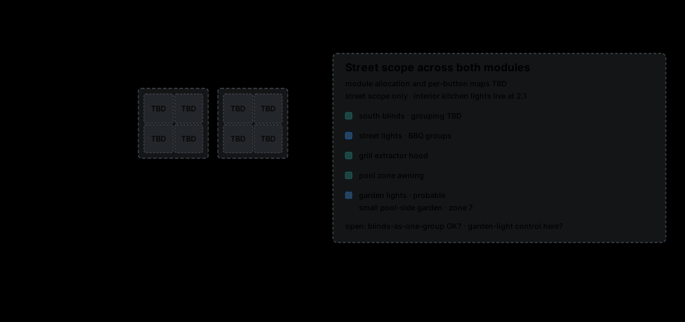
Hosts a horizontal switch-height 2-position frame with 2× F 40, street scope only (the interior kitchen lights live at 2.1).
- To the right (south) of the living room door, operator faces east — this spot also serves the kitchen glass wall / BBQ zone exit.
- Horizontal 2-position frame (the horizontal-row option), 2× F 40 (gang counts TBD); within-row order TBD (both modules street scope, allocation TBD). Verify before drilling: the ~152 mm 2-position frame plus trim clearance fits between the living-room door trim and the glass wall.
- Per-button functions TBD: south blinds, street lights (the BBQ groups), the grill extractor hood (ventilation), the pool zone awning (shading), and probably garden lights (the small pool-side garden, part of zone 7 — rooms).
- Open: street button maps; blinds-as-one-group OK?; whether 2.2 hosts the garden-lights control.
2.3 — Above counter
Hosts the kitchen F 50 RC at 160 cm — the house's one thermostat-height exception.
- To the right of and close to the back hallway door frame (kitchen's north wall), above the counter (first run segment east of the door — house model), operator faces north.
- F 50 height exception: 160 cm center — the 150 cm default conflicts with a decorative border at that height, so this F 50 alone sits above it (mounting heights). The ground-floor LS Touch and every other upper group stay at 150 cm.
- Chosen as the room's most sheltered sensor spot — away from the glass door's open-door air path and the south-glazing sun, the internal sensor being the AC's ambient reference as well.
- The kitchen keeps its own RC alongside the ground-floor hub at 2.1: hubs stay UI-only, control loops live in room devices (wall-controls concept). The kitchen floor-probe conduit routes to the 2.3 RC wall box, not the automation panel. Climate pattern: climate.
- RC gang count: TBD (kitchen scene slots expected on 2.2's F 40s rather than the RC).
- Open: sink one segment east and whatever worktop appliances land below — re-check when the counter plan firms up (the tea station is across the room on the west wall).
- F 40 at 2.3 besides the RC — wanted, at 110 cm center (the counter-clearance height — see below; mounting heights), directly under the RC: same wall spot, aligned group centers, one plumb column, separate frames. Gang count and per-button functions TBD.
- Above-counter implications: no vertical stack — frames grow downward onto the counter — so single position or the horizontal-row option; counter height: 92 cm (house model). British-derived practice (IET Wiring Matters, Autumn 2013, "The highs and lows of accessory mounting" — Approved Document M / IET On-Site Guide Appendix H6) requires the accessory's underside ≥100 mm above the worktop; at 110 cm center the underside lands ~152 mm above the counter, ~52 mm of margin over the requirement. Backsplash alignment still TBD; sink adjacent to the east — horizontal offset to keep, value unrecorded.
3. Living room
- 3.1 — Entrance switches: vertical 3-position frame with an F 40 bus module, F 40 extension module, and voice-satellite provision.
- 3.2 — Kitchen-door cluster: F 50 RC at thermostat height and a switch-height F 40.
- 3.3 — Stairs: horizontal switch-height 2-position frame with an F 40 and voice-satellite provision.
3.1 — Entrance switches
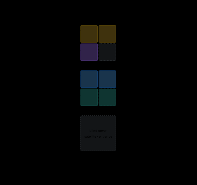
Right near the entrance and the glass wall:
- One vertical 3-position LS frame (~81×223 mm), centered per the frame convention: the frame's center on the 105 cm switch height, its middle position on that line (~112/105/98 cm). Order top→bottom: interior module → street module → voice satellite provision (entrance) — deep box + Cat6 + KNX, blind cover (buttons lead; satellite cover at the bottom per convention). LS ZERO caveat: it keeps standard DIN 49073 boxes but needs dedicated plastering frames/adapters integrated with the finish — finish decision pending before plastering.
- Top: F 40 4-gang bus module — interior + scenes. Function scope (per-button map TBD): main light (both ceiling strips) · dining pendant (dual home — also at the 3.2 kitchen-door cluster) · bra lamp · whole-house scene slots (2× Scene-TBD). Five functions on the 4-gang's eight pressure points — headroom.
- Middle: F 40 4-gang extension module — street. Function scope (per-button map TBD): deck wall lights · pool underwater lights · entrance lights · facade decorative lights · east blind · south blinds (only if south blinds are confirmed). The two blind rockers take two pressure points each and the four light groups one each — the six functions fill the module exactly, no headroom.
- All slaps = disabled (full-surface function set to "no function") — slap scenes removed per the scene policy; slap-hold scene-store disabled. Verify in ETS how disabled-surface middle-presses resolve.
- Orientation convention: operator faces south → east functions on left, south on right.
3.2 — Kitchen-door cluster
Near the kitchen door:
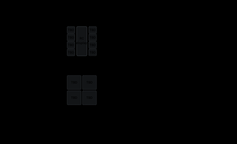
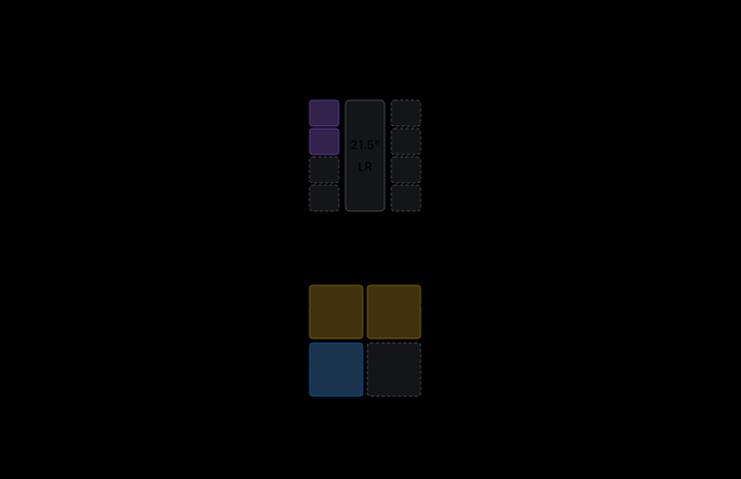
- F 50 RC (LS 5294 D 1ST, 4-gang) at the thermostat height — living room thermostat: full-height central display flanked by two columns of 4 bar buttons — setpoint + / − pair + 6× Scene-TBD, the 4-gang's slot budget (gang-count rule); 4-gang chosen for scene capacity, 3.2 being a central node on the kitchen ↔ living room ↔ pool ways. Mode and AC-fan override via the RC's built-in menu — no mode/fan buttons, per the RC button policy. Internal sensor hosts the living room loop (AC + warm floor); the floor-probe conduit routes to this box; underfloor limit runs here. No light/blind functions ever (wall-controls convention).
- Switch-level frame, 1 position (center at the switch height per the frame convention): F 40 4-gang module. Function scope (per-button map TBD): main light · dining pendant (dual home with 3.1) · deck wall lights · pool underwater lights (dual home with 3.1's street module). Four functions on the eight pressure points — headroom, a Scene-TBD slot the candidate for it. Orientation: operator faces west → south (pool) on left. Slaps unassigned/disabled per policy.
3.3 — Stairs
On the west wall at the foot of the stairs — between the dining zone (south) and the stairs (north):
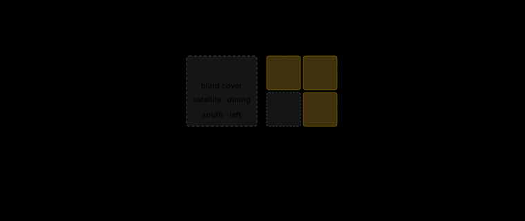
- Switch-level frame, 2 positions, horizontal (the horizontal-row option; both centers at the switch height): north position (operator's right) = F 40 4-gang bus module, stairs side; south position (operator's left) = voice satellite provision (the single dining unit, voice) — deep box + Cat6 + KNX, blind cover, toward the dining zone it serves. No door jamb here — order chosen by served zones, a weak preference.
- Function scope (per-button map TBD): dining pendant (third home — also at 3.1 and 3.2) · main light (both strips) · stairs light (wall fixture + handrail, grouping TBD — the manual point for the presence-driven stairs, mirrored upstairs at the corridor's 10.1 stairs cluster) · floor lamp if its plug-in decision resolves to a dimmed socket. Spatial convention: operator faces west → dining/south on left, stairs/north on right. Four functions on the eight pressure points — headroom.
- Slaps disabled, scene-store off per the scene policy. A Scene-TBD slot is the candidate for the spare capacity — needs scene approval first.
4. Server room
- Wall controls: none inside the server room — its light and extractor-fan manual override are served from back-hallway position 1.1.
- Parked: the HA control panel — if the house gets one, this room is its likely home.
5. Pavel's office
- 5.1 — Entrance: F 50 RC at thermostat height and F 40 at switch height.
- 5.2 — Desk side: horizontal switch-height 2-position frame with an F 40 and voice-satellite provision.
5.1 — Entrance
The entrance cluster, east side of the door (south wall, off the back hallway).
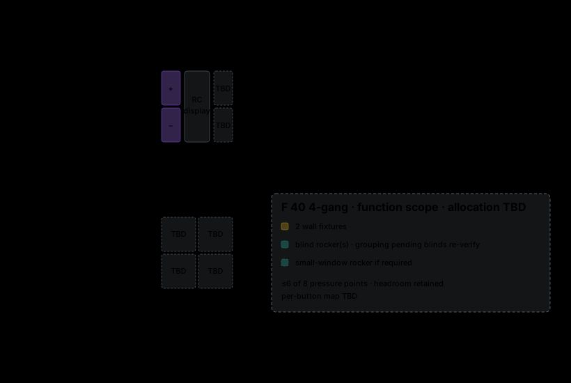
- Thermostat height: F 50 RC 2-gang — setpoint pair + 2 Scene-TBD slots (RC button policy); the interior spot away from the north glazing shelters the internal sensor — the FTXA's ambient reference and the warm-floor loop's input; the office floor-probe conduit routes to this box; underfloor limit runs here (climate).
- Switch height, plumb column below: F 40 4-gang bus module — the two wall fixtures + blind rockers (blind grouping pending the blinds re-verify — rooms); ≤6 of 8 pressure points, headroom holds even if the small window adds a rocker.
- No whole-house scene slots — the backyard sliding door isn't a daily entrance.
- Per-button map TBD.
5.2 — Desk side
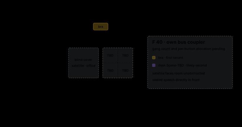
Horizontal desk-side row on the north-wall segment between the window-wall and the small window (eastern third of the wall, to the seated Pavel's left; desk by the east wall — house model), unit facing south; the bra hangs directly above the row (above its center, assumed).
- Horizontal 2-position frame (the horizontal-row option): east position = F 40 bus module (own bus coupler — physically separate position; gang count TBD — the bra is the first tenant, a desk Scene-TBD slot the likely second), nearest the seated reach · west position = satellite provision (deep box + Cat6 + KNX, blind cover) = the office voice satellite's home (voice), facing the room unobstructed with the seated speech right in front. No door jamb here — order a weak preference.
- Verify before drilling: the segment's width is unrecorded — confirm the ~152 mm 2-position frame plus trim clearance fits between the window-wall and the small window.
6. Guest toilet
- 6.1 — Entry passage: single-position switch-height frame with one F 40 4-gang bus module.
6.1 — Entry passage
Single-position switch-height frame, one F 40 4-gang bus module (no stack), on the left-hand wall when entering from the door toward the room proper, within the toilet's short, unobstructed entry passage — approximately 50 cm deep (house model).
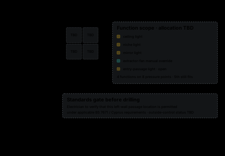
- Verify before drilling: with the electrician, that this left-wall passage location is permitted under the applicable BS 7671 / Cyprus requirements; its status as an outside-control location is TBD.
- Function scope (per-button map TBD): ceiling light · niche light · mirror light · extractor-fan manual override (ventilation) — 4 functions on the 4-gang's 8 pressure points, headroom. Open: whether the entry passage has its own light (a 5th function — still fits).
- No RC — warm-floor actuator zone, loop in the heating actuator (climate); setpoint via the hub pages.
8. BBQ zone
- Candidate 1 — Outdoor-kitchen counter: on the BBQ zone's west wall, above the outdoor-kitchen counter, somewhere between its sink and fireplace, outside both the sink splash area and fireplace heat zone. The position is sheltered from all rain; IP44 is the minimum protection rating because this is an outdoor-kitchen counter near a sink and subject to splashes and cleaning; a higher rating is acceptable.
- Physical envelope and rough-in reserve: two standard frame positions, each roughly one F 40 module in size.
- Mounting height: 110 cm — the counter-clearance height, matching kitchen 2.3's F 40 (mounting heights); the outdoor counter's own height is unrecorded — confirm the ≥100 mm underside clearance once it is.
- Unit: unspecified protected push-button(s) (exterior push-buttons).
- Required function: the local grill-hood manual override (ventilation). Remaining function scope open; full per-group lighting control is not a requirement.
- Final device, mounting form within the two-position reserve, control concept, lighting grouping, and exact spot: TBD with the contractor.
10. Corridor
- 10.1 — Stairs cluster: first-floor LS Touch hub at thermostat height and an F 40 at switch height.
- 10.2 — Kid's-bathroom entrance: single-position switch-height frame with one F 40 4-gang bus module.
10.1 — Stairs cluster
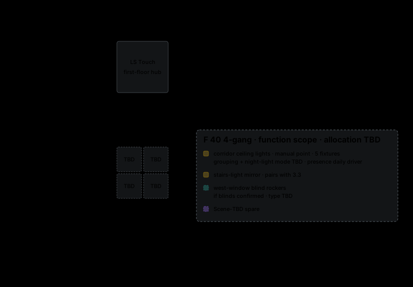
The stairs cluster — first-floor LS Touch hub + switch-height F 40, centered on the approximately 20 cm-wide east-wall pier between the stairs opening and the master-suite entrance.
- The LS Touch and F 40 are aligned in one plumb column. Verify before drilling: the finished clear width, trim clearance, and box fit on the narrow pier.
- Thermostat height: the first-floor LS Touch hub (wall controls) — first-floor climate overview, wet-room floor setpoints, shading/ventilation pages; UI only.
- Switch height, plumb column below: F 40 4-gang bus module — corridor ceiling lights manual point (5 fixtures; grouping + night-light mode TBD; presence-driven as the daily driver — presence) · stairs-light mirror (pairs with 3.3) · west-window blind rockers (if those blinds are confirmed — type TBD, rooms) · Scene-TBD spare.
- Per-button map TBD.
10.2 — Kid's-bathroom entrance
The kid's-bathroom serving position at its entrance (corridor's south end) — single-position switch-height frame, one F 40 4-gang bus module (no stack).
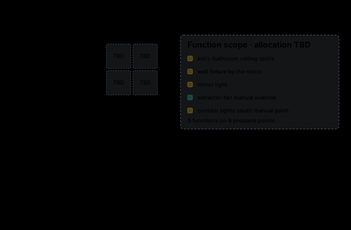
- Function scope (per-button map TBD): kid's bathroom ceiling spots · wall fixture by the mirror · mirror light · kid's-bathroom extractor-fan manual override (ventilation) · corridor lights south manual point — 5 functions on the 4-gang's 8 pressure points.
- No controls inside the wet room (BS zone rule — positions).
Room-wide notes
- No RC — warm-floor actuator zone, loop in the heating actuator (climate); wet-room floor setpoints via the 10.1 hub.
11. Laundry room
- 11.1 — Door: single-position switch-height frame with one F 40 bus module.
11.1 — Door
Single-position switch-height frame with one F 40 bus module. On the west side of the laundry's sliding door; the door panel moves east when opened (house model).
- Function scope (per-button map TBD): laundry ceiling light · extractor-fan manual override (ventilation). Gang count TBD.
- No RC — the laundry warm floor shares the corridor's actuator loop (climate); setpoint via the first-floor hub at corridor 10.1.
12. Boudoir
- 12.1 — Entrance: F 50 RC at thermostat height and F 40 at switch height.
- 12.2 — Above desk: horizontal 3-position frame with two mains sockets and a voice-satellite provision.
12.1 — Entrance
Entrance cluster with an F 50 RC at thermostat height and an F 40 bus module at switch height, on the left-hand side when entering through the boudoir doorway. There is no entrance hallway; this is a normal doorway.
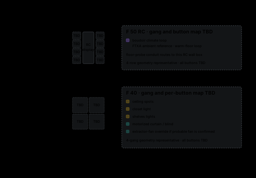
- F 50 RC: hosts the boudoir climate loop — the FTXA ambient reference and the warm-floor loop; the floor-probe conduit routes to this box (climate). Gang count TBD.
- F 40 function scope (per-button map TBD): ceiling spots · closet light · shelves lights · motorized curtain/blind · extractor-fan manual override (ventilation). Gang count TBD.
12.2 — Above desk
Satellite provision in the electrical-socket section above the desk, at the east end of the south wall (house model).
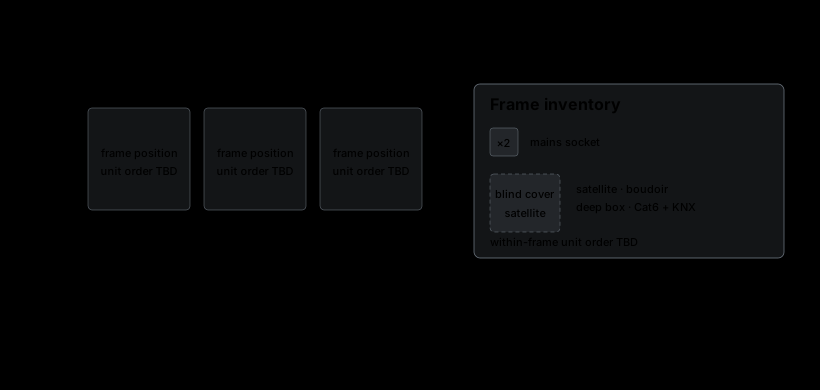
- One horizontal 3-position Jung frame: 2 mains sockets + the satellite provision under a blind cover.
- Each position has its own recessed flush box; the satellite position uses a deep box + Cat6 + KNX. The box/partition solution must preserve mains/extra-low-voltage separation; exact hardware depends on the finish choice (LS ZERO uses standard DIN 49073 boxes but requires dedicated plastering frames/adapters) and is TBD with the electrician.
- The socket/satellite row sits at 90 cm centerline above finished floor, above the desk (mounting heights). The desk height itself is unrecorded. No wall-control module.
13. Master bedroom hallway
- 13.1 — Suite entrance: single-position switch-height frame with one F 40 4-gang bus module.
- 13.2 — Master bathroom: single-position switch-height frame with one F 40 4-gang bus module.
- 13.3 — Master-bedroom entrance: F 50 RC at thermostat height and a horizontal switch-height F 40 + Magnetic Charger frame.
Three positions along the corridor→bedroom run.
13.1 — Suite entrance
Single-position switch-height frame, one F 40 4-gang bus module. South wall, west of the dressing-room (16) door, near the master-suite entrance (corridor side).
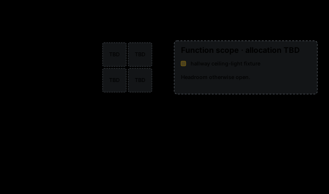
- Function scope (per-button map TBD): the hallway's one ceiling-light fixture — natural fit right at the entrance (flip-as-you-walk-in), mirroring the corridor's 10.1. Headroom otherwise open.
13.2 — Master bathroom
Single-position switch-height frame, one F 40 4-gang bus module (no stack). South wall, east of the master-bathroom (15) door.
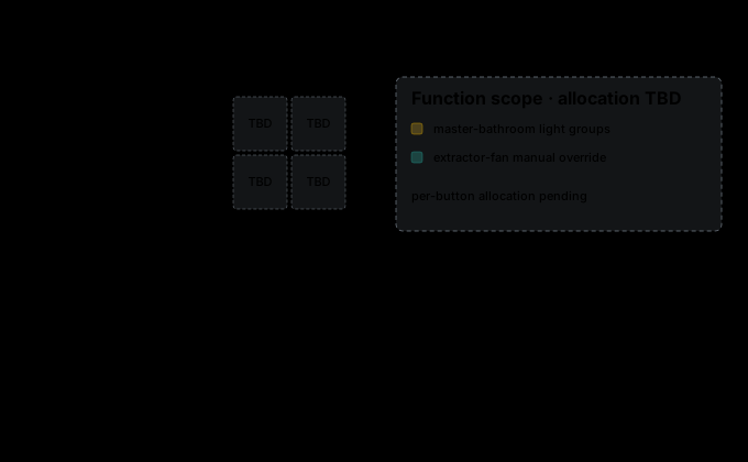
- Function scope (per-button map TBD): the bathroom's light groups · bathroom extractor-fan manual override (ventilation).
- No controls inside the wet room itself (BS zone rule — positions).
13.3 — Master-bedroom entrance
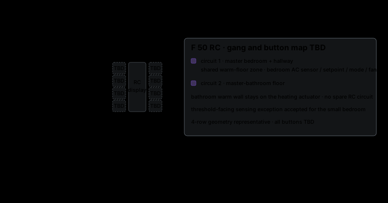
F 50 RC at thermostat height and a horizontal 2-position frame at switch height, aligned in one plumb column, on the north wall of the hallway, near its connection to the master bedroom (14), at the hallway's east end.
- Thermostat height: F 50 RC — hosts both the master bedroom's and the master bathroom's climate loops on its two independent controller circuits (wall-controls concept): circuit 1 = master bedroom + this hallway (one shared warm-floor zone, plus the bedroom's AC sensor/setpoint/mode/fan UI); circuit 2 = master bathroom's floor (the bathroom has no AC of its own). The bathroom's separate warm-wall zone stays on the heating actuator, not this RC — no spare circuit for it (climate).
- A deliberate exception to the usual pattern (every other RC sits inside the room its primary circuit senses): the bedroom is small enough that a threshold-facing unit was judged to sense it adequately.
- Switch height, centered at 105 cm: horizontal 2-position frame with one F 40 bus module and one Jung Magnetic Charger insert. F 40 function scope and within-frame order: TBD.
- The Magnetic Charger needs a standard flush box and mains feed. The box/partition solution must preserve mains/extra-low-voltage separation between it and the F 40. Verify before drilling: the exact mixed-frame boxes/adapters with the electrician.
14. Master bedroom
- 14.1 — South-glazing cluster: single-position switch-height frame with one F 40 4-gang bus module.
- 14.2 — West bedside: horizontal 3-position frame with a type-G/USB-C socket, Jung Magnetic Charger, and F 40.
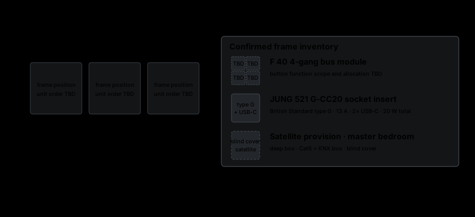
- 14.3 — East bedside: horizontal 3-position frame with an F 40, type-G/USB-C socket, and voice-satellite provision.
14.1 — South-glazing cluster
Single-position switch-height frame with one F 40 4-gang bus module. On the west wall immediately south of the hallway opening (the opening is centered on that wall), close to the south sliding glass wall; operator faces west → north on the right, south on the left.
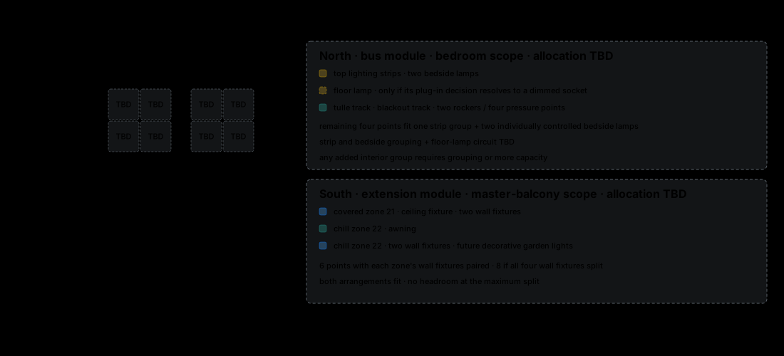
- Function scope (per-button map TBD): master-balcony functions — covered zone 21's ceiling fixture and two wall fixtures · chill zone 22's awning, two wall fixtures, and future decorative garden lights. This uses six pressure points if each zone's wall-fixture pair is grouped, or all eight if all four wall fixtures are separate; both arrangements fit, with no headroom at the maximum split.
- The indoor control point for zones 21–22 remains here. The chill zone (22) additionally gets its own local wall group (zone 22) — which of the zone-22 functions move there, and which stay mirrored here, is TBD.
- Bedroom-function allocation across 13.3, 14.2, and 14.3 is TBD: top lighting strips · two bedside lamps · floor lamp if its plug-in decision resolves to a dimmed socket · tulle curtain track · blackout curtain track.
14.2 — West bedside
Horizontal 3-position frame on the north wall, above the west nightstand (headboard against this wall), at 70 cm centerline above finished floor.
- Frame order, left to right: one JUNG 521 G-CC20 socket insert (British Standard type G, 13 A, with 2× USB-C; 20 W total) · one Jung Magnetic Charger insert · one F 40 4-gang bus module.
- F 40 function scope: TBD.
- The Magnetic Charger needs a standard flush box and mains feed. The box/partition solution must preserve mains/extra-low-voltage separation between the socket/charger and the F 40. Verify before drilling: the exact mixed-frame boxes/adapters with the electrician.
- The 521 G-CC20 insert is announced for Q4 2026; exact centre plates, finish, and other visible design details are deliberately deferred.
14.3 — East bedside
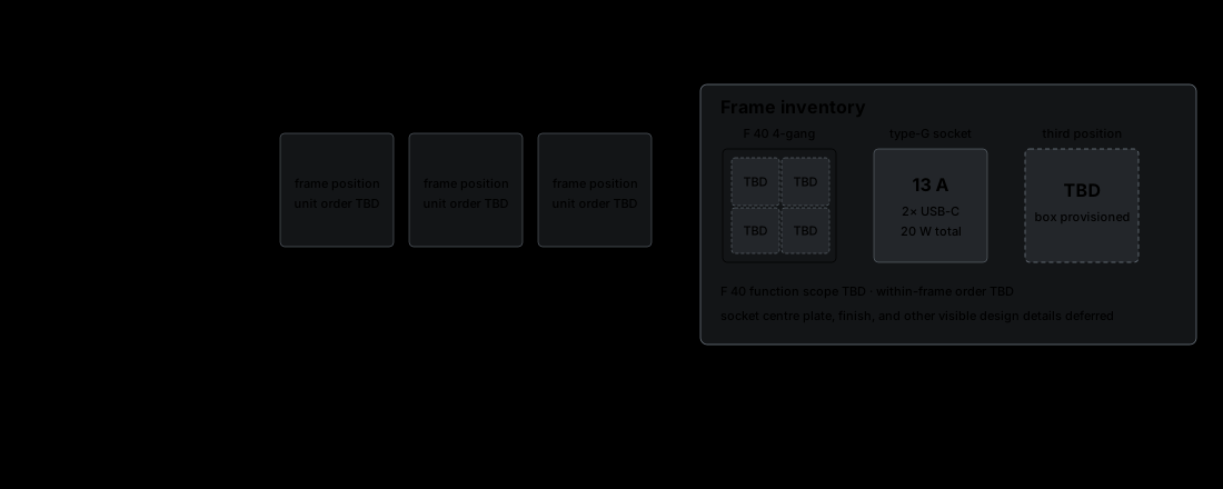
Horizontal 3-position frame on the north wall, above the east nightstand (headboard against this wall), at 70 cm centerline above finished floor.
- Frame inventory: one F 40 4-gang bus module · one JUNG 521 G-CC20 socket insert (British Standard type G, 13 A, with 2× USB-C; 20 W total) · one satellite provision (deep box + Cat6 + KNX, blind cover) = the master bedroom's one satellite (voice).
- The east position was chosen for the satellite because it is farthest from the west-wall hallway opening and faces the full room.
- F 40 function scope and within-frame order: TBD. Exact centre plates, finish, and other visible design details are deliberately deferred.
- The box/partition solution must preserve mains/extra-low-voltage separation between the type-G socket and satellite provision. Verify before drilling: the exact mixed-frame boxes/adapters, with the electrician. The 521 G-CC20 is announced for Q4 2026.
16. Dressing room
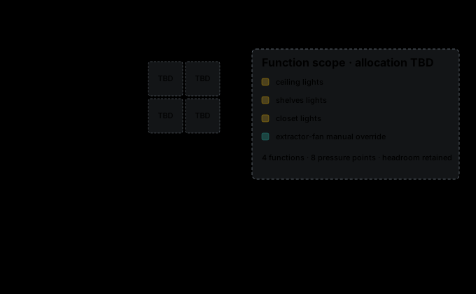
- 16.1 — Entrance: single-position switch-height frame with one F 40 4-gang bus module.
16.1 — Entrance
Single-position switch-height frame, one F 40 4-gang bus module (no stack).
- On the north wall immediately left of the door when viewed from inside the dressing room (the west side of the opening); operator faces north (house model).
- Function scope (per-button map TBD): ceiling lights · shelves lights · closet lights · extractor-fan manual override (ventilation). Four functions on the 4-gang's eight pressure points, leaving headroom.
- No RC: the room has no AC, and its warm floor — its own zone — regulates in a heating-actuator channel (climate).
17. Kid's bedroom
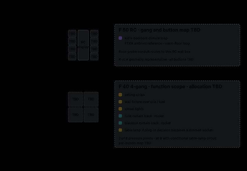
- 17.1 — Entry passage: F 50 RC at thermostat height and F 40 4-gang at switch height.
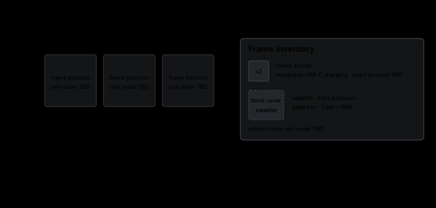
- 17.2 — East bedside: horizontal 2-position frame with an F 40 and a mains socket with integrated USB-C charging, at 70 cm.
- 17.3 — Above desk: horizontal 3-position frame with two mains sockets with integrated USB-C charging and the room's satellite provision, at 85 cm.
17.1 — Entry passage
Entrance cluster with an F 50 RC at thermostat height and an F 40 4-gang bus module at switch height, aligned in one plumb column as separate frames.
- On the south wall of the short, approximately 50 cm-deep entry passage, about 20 cm from its opening into the main room; operator faces south. The entrance door opens toward the north wall, leaving the controls clear (house model).
- F 50 RC: hosts the kid's-bedroom climate loop — FTXA ambient reference and warm-floor loop; the floor-probe conduit routes to this box (climate). Gang count TBD.
- F 40 function scope (per-button map TBD): ceiling strips · wall fixture over the crib/bed · closet lights · tulle curtain track · blackout curtain track · table lamp if its plug-in decision resolves to a dimmed socket. The two curtain rockers consume four pressure points; the other recorded functions bring the 4-gang to seven points, or all eight if the table lamp gets a dedicated circuit.
17.2 — East bedside
Horizontal 2-position frame on the east wall above the nightstand, at 70 cm centerline above finished floor.
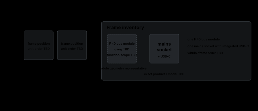
- Frame inventory: one F 40 bus module · one mains socket with integrated USB-C charging. The socket's exact product/model is TBD.
- F 40 gang count, function scope, and within-frame order: TBD.
- Verify before drilling: the exact common-frame box, adapters, and mains/KNX separation with the electrician.
17.3 — Above desk
Horizontal 3-position frame on the north wall above the desk, at 85 cm centerline above finished floor.
- Frame inventory: two mains sockets, each with integrated USB-C charging · one satellite provision (deep box + Cat6 + KNX, blind cover) = the kid's bedroom's one satellite (voice). Exact socket products/models are TBD.
- Within-frame order: TBD. No wall-control module.
- The box/partition solution must preserve mains/extra-low-voltage separation. Verify before drilling: the exact mixed-frame boxes/adapters with the electrician.
18. Ekaterina's office
- 18.1 — Entry passage: F 50 RC at thermostat height and F 40 4-gang at switch height.
- 18.2 — Above desk: horizontal 3-position frame with two mains sockets and the room's satellite provision.
- 18.3 — Glazing side: single-position switch-height frame with one F 40 for the balcony lights, at 105 cm.
18.1 — Entry passage
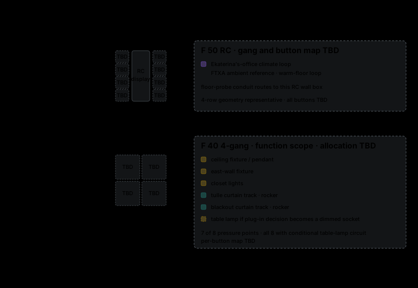
Entrance cluster with an F 50 RC at thermostat height and an F 40 4-gang bus module at switch height, aligned in one plumb column as separate frames.
- Same entrance geometry as the kid's bedroom: on the south wall of a short, approximately 50 cm-deep entry passage, about 20 cm from its opening into the main room; operator faces south. The entrance door opens toward the north wall, leaving the controls clear (house model).
- F 50 RC: hosts Ekaterina's-office climate loop — FTXA ambient reference and warm-floor loop; the floor-probe conduit routes to this box (climate). Gang count TBD.
- F 40 function scope (per-button map TBD): ceiling fixture / pendant · east-wall fixture · closet lights · tulle curtain track · blackout curtain track · table lamp if its plug-in decision resolves to a dimmed socket. The two curtain rockers consume four pressure points; the other recorded functions bring the 4-gang to seven points, or all eight if the table lamp gets a dedicated circuit.
18.2 — Above desk
Horizontal 3-position frame above the middle of the west-wall desk, at 85 cm centerline above finished floor (house model).
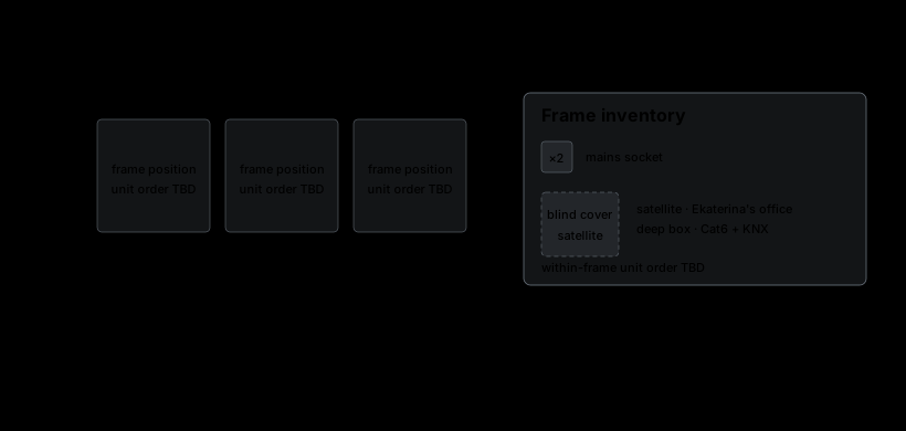
- Frame inventory: two mains sockets + the room's one satellite provision under a blind cover.
- Each position has its own recessed flush box; the satellite position uses a deep box + Cat6 + KNX. The box/partition solution must preserve mains/extra-low-voltage separation; exact hardware depends on the finish choice (LS ZERO uses standard DIN 49073 boxes but requires dedicated plastering frames/adapters) and is TBD with the electrician.
- Within-frame order: TBD. No wall-control module.
18.3 — Glazing side
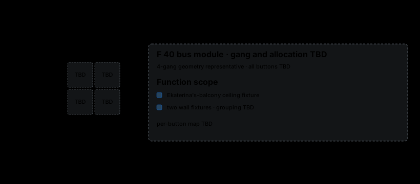
Single-position switch-height frame with one F 40 bus module, at 105 cm centerline above finished floor. On the west wall near the south glazing; the position remains exposed and reachable in every curtain position.
- Function scope (per-button map TBD): Ekaterina's-balcony ceiling fixture · two wall fixtures. Gang count and wall-fixture grouping: TBD.
- The balcony-light control is homed here rather than at entrance position 18.1.
22. Chill zone
- Candidate 1 — Wall group: a local group of unspecified protected push-button(s) on the chill zone's wall; two adjacent boxes/positions reserved at 105 cm; exact spot and function scope TBD.
- Unit: unspecified IP66-or-higher protected push-button(s) (exterior push-buttons) — the zone is uncovered and the wall position receives direct rain (house model).
- Function scope open: the zone's awning, its two wall fixtures, and the future decorative garden lights are the candidates (rooms 22); master-bedroom 14.1 stays the indoor control point for zones 21–22, so the split between the two is TBD.
- Physical envelope and rough-in reserve: two adjacent boxes/positions. If the selected IP66 device ultimately needs only one, the second remains covered/reserved while maintaining IP66-or-higher protection.
- Mounting height: 105 cm — the switch default (mounting heights).
- Exact spot: TBD.